How to Select a Valve Actuator: Types of Valve Actuators, Appropriate Sizing, Safety Criteria, and More
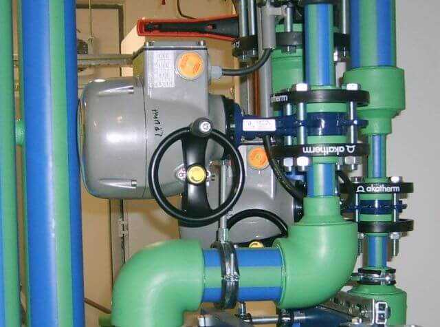

Valve actuators are a type of control valve, and there are many options available to meet plant-wide and individual automation requirements. While simple in concept, consisting of a box with an input, output, and a mechanism to operate a valve, there are actually quite a few considerations in choosing the right valve actuator. And because the valve actuator plays a more significant role in a valve’s overall performance in the control loop, it’s a decision that engineers shouldn’t take lightly.
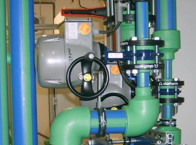
Image via Wikimedia Commons
In this guide, we’ll discuss the two primary types of valve operation, types of valve actuators, important valve actuator functions, valve sizing information, and the key considerations in selecting the right valve actuator. Use the links below to navigate to a specific section:

There are dozens of types of control valves. From the perspective of a valve actuator, however, there are two primary types of valve operation. Understanding how a valve operates is the first step in choosing the appropriate actuator.
Just as there are many types of valves, there are several specific types of valve actuators. Most, however, fall into a few common categories, based on the type of power applied and the type of movement required:
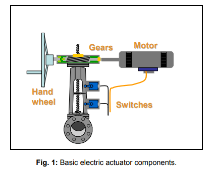
Screenshot via Valve-World.net
Pneumatic and hydraulic actuators are described together and operate similarly; however, they differ slightly in how the cylinder is moved. Hydraulic actuators move the cylinder with an incompressible liquid from a pump, while pneumatic actuators move the cylinder using pressurized air. Pneumatic actuators aren’t as practical for large equipment that requires large bore cylinders because of compressed air consumption.
Hydraulic actuators, on the other hand, can have a higher cost per unit compared to pneumatic and electric actuators. They also tend to leak fluid, and they require a variety of companion parts including motors, pumps, release valves, fluid reservoirs, heat exchangers, and noise-reduction equipment.
Valve actuators can also be categorized as diaphragm actuators, direct-acting and reverse-acting actuators, direct-acting diaphragm actuators, field-reversible multi-spring actuators, and piston actuators, although there are other types as well.
All valve actuators must perform several functions including:
Now that we’ve covered the basic types of valves and valve actuators, as well as the main functions valve actuators must perform, there are a few important considerations to weigh when selecting the appropriate actuator for your application. There are a variety of factors to consider, ranging from usage factors, to sizing, supply pressure requirements, safety and reliability, cost considerations, and more.
Usage factors are a significant considerations in selecting the right valve actuator. These factors include:
The National Electric Manufacturers Association (NEMA) has established guidelines on the construction and installation of electric valve actuators in hazardous areas. This guideline states:
VII Hazardous Location Class I (Explosive Gas or Vapor)
Meets application requirements of National Electric Code; conforms with specifications of Underwriters’ Laboratories, Inc. used for atmosphere containing gasoline, hexane, naphtha, benzene, butane, propane, acetone, benzol, lacquer-solvent vapors, natural gas.
Most manufacturers of electric valve actuators offer NEMA VII-compliant versions of their standard products to meet the requirements for hazardous applications. In some cases, a more cost-effective option is to use electric controls with pneumatic valve actuators. However, when feasible, pneumatic actuators are generally the safer and more practical choice.
Force refers to the torque requirement of the valve, meaning the amount of force required to move the valve from the open to the closed position. In a sliding stem valve, the force required would be a linear push-and-pull force; multi-turn or part-turn valves require a rotary force. Determining the amount of force required depends on a number of factors such as:
The size and design of the valve and the differential pressure across the valve are also considerations, as well as the stem packing friction, media temperature, and the mechanical characteristics of both the valve and the valve stem. Note that for quarter-turn valves, it’s not possible to calculate the valve’s torque demand accurately. Instead, physical measurement of each valve size under various differential pressure conditions is required.
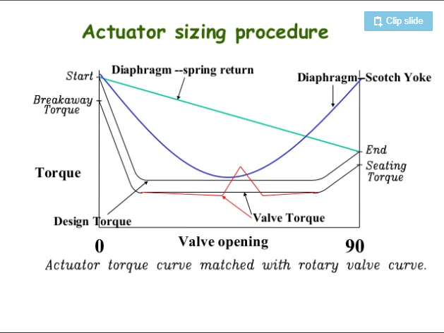
Screenshot via Sizing and Selection of Actuators for Valves, SlideShare
Due to the complexity involved in properly sizing valve actuators, it’s imperative that actuators are sized by technically trained experts. Simply opting for an oversized actuator isn’t a safeguard, either; an oversized valve actuator can damage the stem of the valve (unless additional components such as relief valves are used), plus it’s wasteful spending. An undersized actuator simply won’t be able to operate the valve on demand, which is particularly important in Emergency Shutdown Valves (ESDVs).
Minimum and maximum supply pressure are among the most important sizing factors to consider. Normal pressure, a metric often provided, should never be used to size an actuator. An actuator must be able to develop enough torque to operate the valve at the minimum supply pressure, ensuring that it functions properly even when supply pressure is at its lowest point. Maximum pressure must also be considered, as it’s imperative that the actuator be able to handle the maximum potential pressure safely. Regulators and relief valves may be used in applications in which the actuator is oversized or unable to handle the maximum supply pressure safely.
The speed of operation required dictates the power requirements of the actuator. It takes more power to perform an operation (such as fully opening or closing a valve) in less time, for instance.
Pneumatic actuators have an advantage in that it’s easier to control their speed. The easiest way to implement speed control in a pneumatic actuator is to fit it with a needle valve, or a variable orifice, at the air pilot exhaust port. Electric actuators have geared motors and therefore it’s difficult (impossible, really) to control the speed of these actuators without making gear adjustments. Pulsing circuits can be added in some cases to allow for slower operation.
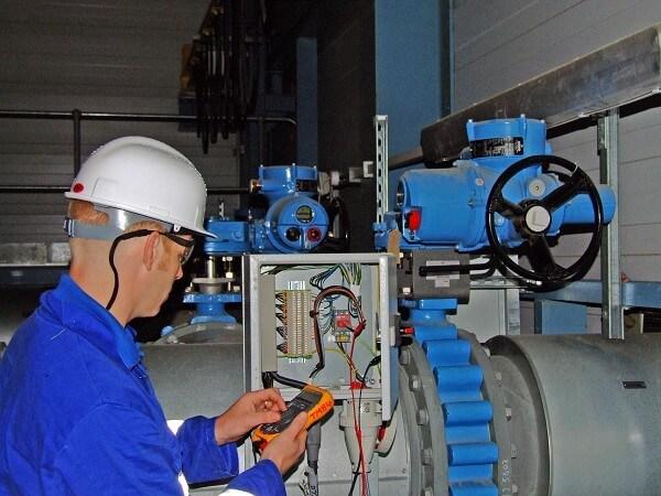
Image via Wikipedia
For electric actuators, the required operating speed determines the motor power required. For fluid power actuators (pneumatic and hydraulic actuators), the required operating speed determines the necessary size of supply and exhaust lines in addition to the size of the direction control valve.
The frequency of operation (or duty) impacts mechanical drive durability and the robustness of the controller. Obviously, valves that operate infrequently (such as isolating or regulating duty valves) mean less wear and tear on mechanical components and controls. Other valves, however, such as modulating process valves, operate on a near-constant or continuous basis, requiring a more durable valve and actuator assembly.
Actuator capability is generally defined as a specified number of starts per hour. According to the ISA Guidelines for the Specification of Electric Valve Actuators, “The reversing contactor as standard should be rated for a minimum of 60 motor starts per hour. Optional solid state reversing contactors should be electrically interlocked and be available for high rate modulating service and rated for minimum of 1200 starts per hour.”
Screenshot via Indelac Controls, Inc.
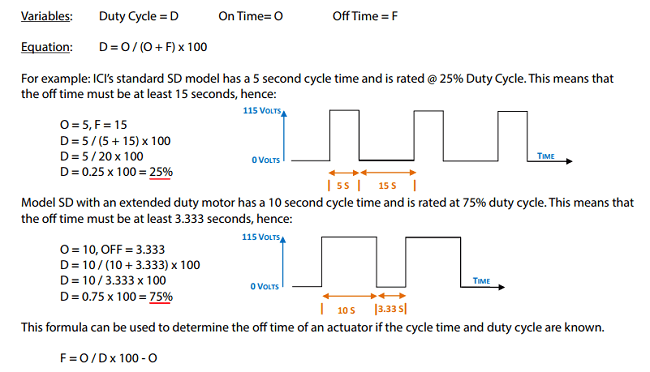
Another general rule of thumb is based on the duty cycle:
In certain applications, such as hazardous environments, guidelines such as NEMA VII aim to improve safety by requiring certain precautions for different types of actuators. Safety should always be a consideration when selecting a valve actuator, and when possible, the safest and most reliable option based on the application specifications should be used. An actuator should be able to maintain the fail-safe position should a fire break out, for example.
However, in some situations, the ideal actuator can’t be used due to mitigating circumstances. When a different type of actuator must be used than the most ideal solution, there are often additional components that can be added to improve safety and meet regulatory specifications.
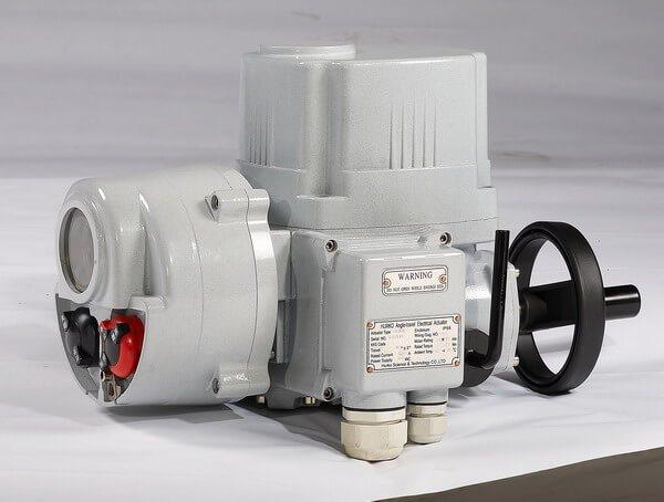
Image via Wikimedia Commons
For example, pneumatic actuators can be stalled indefinitely without issue, but electric actuators cannot be stalled without risking damage to the motor due to excessive current generating heat in the motor. To protect the device, torque switches or heat and current sensors can be used.
Spring returns, or fail-safe options, are another safety component often specified in process industries. Spring returns drive the valve to a pre-determined safe position in the event of a power or signal failure. With pneumatic actuators, this is both a practical and inexpensive option. Accumulator tanks may be installed to store air pressure when spring returns cannot be used (which is sometimes the case with large or heavy actuators).
Most electric actuators aren’t available with a spring-return option, but a battery backup is often a viable fail-safe option for these actuators. Or, an electro-hydraulic actuator may be used to achieve spring-return functionality, requiring only an electric power supply. This is done by energizing a hydraulic pump which pressurizes a spring-return cylinder, driving the actuator to the original position in the event of a power failure.
All of the factors discussed above impact the cost of a valve actuator. In general, the greater the torque required, the more power necessary for operation, the larger and more expensive the actuator. While selecting the proper valve actuator for the application, including any additional components required for safe and desirable operation, may mean higher upfront costs, the final configuration will benefit from greater reliability and durability. Writing clear and unambiguous technical specifications, being diligent about quality control, and ensuring adequate supplier qualifications are essential steps in procuring the right actuator for your application.
The wrong actuator won’t just fail to adequately operate the valve but can lead to damage to the valve stem and the valve itself, as well as introduce unnecessary safety risks. Choosing the right valve actuator means fewer unexpected shutdowns and less frequent actuator and valve replacements, and ultimately lower long-term costs.
Our sales engineers are experts in automatic asset tracking, tagging and identification,a nd can answer all your questions. Get in touch now.
Lets Talk ›